- 您现在的位置:买卖IC网 > Sheet目录310 > AP8801M8G-13 (Diodes Inc)IC LED DRIVER HIGH BRIGHT 8MSOP
�� �
�
�AP8801�
�500mA� LED� STEP-DOWN� CONVERTER�
�Application� Information� (cont.)�
�PWM� Dimming� of� LED� Current�
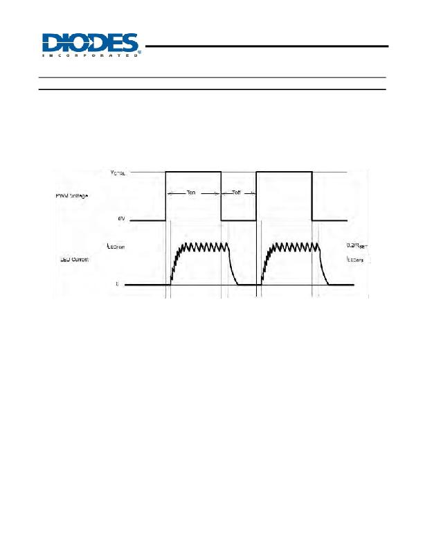
�When� a� low� frequency� PWM� signal� with� voltages� between� 2.5V� and� a� low� level� of� zero� is� applied� to� the� CTRL� pin� the� output� current� will� be�
�switched� on� and� off� at� the� PWM� frequency.� The� resultant� LED� current� I� LEDavg� will� be� proportional� to� the� PWM� duty� cycle.� See� figure� 18.�
�A� Pulse� Width� Modulated� (PWM)� signal� with� a� max� resolution� of� 8-bit,� can� be� applied� to� the� CTRL� pin� to� change� the� output� current� to� a� value�
�above� or� below� the� nominal� average� value� set� by� resistor� R� SET� .�
�To� achieve� this� resolution� the� PWM� frequency� has� to� be� lower� than� 500Hz.� The� ultimate� resolution� will� be� determined� by� the� number� of�
�switching� cycles� required� to� get� back� to� nominal� LED� current� once� the� PWM� voltage� is� high� relative� to� PWM� frequency.� Lower� switching�
�frequencies� and� higher� PWM� frequencies� will� result� in� lower� PWM� dimming� dynamic� ranges.�
�Figure.� 18� Low� Frequency� PWM� Operating� Waveforms�
�There� are� different� ways� of� accomplishing� PWM� dimming� of� the� AP8801� LED� current:�
�Directly� Driving� CTRL� Input�
�A� Pulse� Width� Modulated� (PWM)� signal� with� duty� cycle� DPWM� can� be� applied� to� the� CTRL� pin� to� adjust� the� output� current� to� a� value� above�
�or� below� the� nominal� average� value� set� by� resistor� R� SET� .� When� driving� the� CTRL� with� a� voltage� waveform� care� should� be� taken� not� to�
�exceed� a� drive� voltage� of� 2.5V� (where� extra� brightness� is� required)� or� 1.25V� if� a� maximum� of� 100%� brightness� is� required.�
�A� way� of� avoiding� over-driving� the� CTRL� pin� is� use� an� open� collector/drain� driver� to� drive� the� CTRL� pin.�
�Driving� the� CTRL� Input� via� Open� Collector� Transistor�
�The� recommended� method� of� driving� the� CTRL� pin� and� controlling� the� amplitude� of� the� PWM� waveform� is� to� use� a� small� NPN� switching�
�transistor.� This� uses� the� internal� pull-up� resistor� between� the� CTRL� pin� and� the� internal� voltage� reference� to� pull-up� CTRL� pin� when� the�
�external� transistor� is� turned� off.�
�Driving� the� CTRL� Input� from� a� Microcontroller�
�If� the� CTRL� pin� is� driven� by� a� MOSFET� (either� discrete� or� open-drain� output� of� a� micro-controller)� then� Schottky� diode� maybe� be� required�
�due� to� high� Gate� /� Drain� capacitance,� which� could� inject� a� negative� spike� into� CTRL� input� of� the� AP8801� and� cause� erratic� operation� but� the�
�addition� of� a� Schottky� clamp� diode� (eg.� Diodes� Inc.� SD103CWS)� to� ground� and� inclusion� of� a� series� resistor� (3.3k)� will� prevent� this.�
�AP8801�
�Document� number:� DS31765� Rev.� 7� -� 2�
�9� of� 14�
�www.diodes.com�
�June� 2012�
�?� Diodes� Incorporated�
�发布紧急采购,3分钟左右您将得到回复。
相关PDF资料
AP8802HSP-13
IC LED DRIVER HIGH BRIGHT 8SOIC
AP8802SPG-13
IC LED DRIVER HIGH BRIGHT 8SOIC
AP8803WTG-7
IC LED DRIVER CONN CURR TSOT23-5
APEK4402KLP-01-T-DK
BOARD EVAL FOR A4402
APP-001-15AMP
PLUG AUTO PWR BLACK W/LED 15AMP
APP-001-20AMP
AUTO PLUG 12VOLT WITH 20AMP FUSE
APP-001-VO
PLUG AUTO PWR BLACK W/LED IND
APP-001
PLUG AUTO PWR BLACK W/LED IND
相关代理商/技术参数
AP8801SG-13
功能描述:LED照明驱动器 28V, 350mA LED DC/DC Converter RoHS:否 制造商:STMicroelectronics 输入电压:11.5 V to 23 V 工作频率: 最大电源电流:1.7 mA 输出电流: 最大工作温度: 安装风格:SMD/SMT 封装 / 箱体:SO-16N
AP8802
制造商:DIODES 制造商全称:Diodes Incorporated 功能描述:1A LED Step-down Converter
AP8802_0912
制造商:DIODES 制造商全称:Diodes Incorporated 功能描述:1A LED Step-down Converter
AP8802EV1
功能描述:AP8802 1, Non-Isolated Output LED Driver Evaluation Board 制造商:diodes incorporated 系列:- 零件状态:有效 电流 - 输出/通道:700mA 输出和类型:1,非隔离 电压 - 输出:- 特性:可调光 电压 - 输入:8 V ~ 45 V 所含物品:板 使用的 IC/零件:AP8802 标准包装:1
AP8802EV2
功能描述:AP8802 1, Non-Isolated Output LED Driver Evaluation Board 制造商:diodes incorporated 系列:- 零件状态:有效 电流 - 输出/通道:1A 输出和类型:1,非隔离 电压 - 输出:- 特性:可调光 电压 - 输入:8 V ~ 45 V 所含物品:板 使用的 IC/零件:AP8802 标准包装:1
AP8802EV3
功能描述:AP8802 1, Non-Isolated Output LED Driver Evaluation Board 制造商:diodes incorporated 系列:- 零件状态:有效 电流 - 输出/通道:1A 输出和类型:1,非隔离 电压 - 输出:- 特性:可调光 电压 - 输入:8 V ~ 45 V 所含物品:板 使用的 IC/零件:AP8802 标准包装:1
AP8802FNG-7
功能描述:LED照明驱动器 28V, 350mA LED DC/DC Converter RoHS:否 制造商:STMicroelectronics 输入电压:11.5 V to 23 V 工作频率: 最大电源电流:1.7 mA 输出电流: 最大工作温度: 安装风格:SMD/SMT 封装 / 箱体:SO-16N
AP8802H
制造商:DIODES 制造商全称:Diodes Incorporated 功能描述:60V 1A LED Step-down Converter